
Why Crankshaft Sensor Failure Matters: Impact on Engine Performance and Reliability
The crankshaft position sensor (CPS) serves as the engine's neurological command center—synchronizing ignition timing and fuel injection with millisecond precision. When it fails, consequences cascade across critical systems:
- Sudden engine stalling, especially at highway speeds, creates hazardous driving conditions
- Persistent no-start conditions leave drivers stranded and incur costly towing
- Misfires and power loss from mistimed combustion accelerate wear on pistons, bearings, and valves
- Fuel efficiency drops 15–30%, as unoptimized injection cycles waste fuel and increase emissions
- Unburned fuel entering the exhaust can overheat and destroy the catalytic converter—a $740+ repair (Ponemon Institute, 2023)
| Failure Impact | Engine System Affected | Long-Term Consequence |
|---|---|---|
| Timing errors | Ignition coils/spark plugs | Pre-ignition damage |
| Injection miscalibration | Fuel injectors | Cylinder wall scoring |
| RPM miscalculation | Transmission control | Premature clutch wear |
Most parts tend to wear down slowly over time, but when it comes to CPS failures, things can go south pretty suddenly. According to data from SAE International on diagnostics, about three out of every four field failures happen because of two main issues: thermal stress caused by being too close to hot exhaust manifolds, and electromagnetic interference from those powerful ignition systems running at high voltage levels. Want to avoid getting caught off guard? Regular checks matter a lot here. And don't wait until something breaks before replacing parts either. Stick with what the manufacturer recommends for replacements if possible. These kinds of preventive measures really help stop small problems from turning into bigger headaches down the road.
Preventive Crankshaft Sensor Maintenance and OEM-Based Replacement Guidelines
Recommended replacement intervals by vehicle platform and driving conditions
Manufacturers specify crankshaft sensor replacement intervals based on engine architecture, thermal load, and duty cycle—not generic mileage rules. Compact turbocharged engines typically require inspection every 60,000 miles; heavy-duty diesel platforms may extend to 100,000 miles. Critical variables include:
| Vehicle Platform | Standard Interval | High-Stress Conditions* |
|---|---|---|
| Performance Turbo | 60,000 miles | 40,000 miles |
| Standard V6/V8 | 80,000 miles | 60,000 miles |
| Commercial Diesel | 100,000 miles | 75,000 miles |
| *High-stress includes extreme ambient temperatures, frequent short trips (<5 miles), or sustained towing loads |
Stop-and-go traffic accelerates wear through repeated thermal cycling, while coastal or high-humidity environments raise corrosion risk—especially at connectors. Always defer to OEM service documentation, as sensor tolerances, mounting geometry, and signal thresholds vary significantly between manufacturers (e.g., Honda's variable-reluctance sensors vs. GM's Hall-effect units).
Monitoring ECM trouble codes and live-data trends for early crankshaft sensor degradation
Early detection relies on interpreting both diagnostic trouble codes (DTCs) and real-time ECM data—not just P0335 (“Crankshaft Position Sensor ‘A’ Circuit”), but how the signal behaves under load. Key indicators include:
- RPM signal instability: Fluctuations exceeding ±3% during steady-state operation
- Signal dropout frequency: More than two dropouts per driving cycle suggest connector or harness issues
- Startup correlation variance: A >5° discrepancy between crankshaft and camshaft position signals at cranking indicates timing drift
Thermal degradation typically appears as increasing signal noise during warm-up; EMI-induced faults spike during high-load acceleration. Establishing baseline readings during routine maintenance enables comparative analysis—reducing misdiagnosis and cutting average diagnostic time by 65%, per ASE-certified technician field reports.
Diagnosing a Failing Crankshaft Sensor: Symptoms, Causes, and Real-World Failure Patterns
Key symptoms: no-start, intermittent stalling, and tachometer drop-outs — validated against SAE field data
SAE field studies across 12,000 vehicles confirm three hallmark symptoms accounting for 87% of verified CPS failures:
- No-start condition: Occurs when the sensor transmits no position data to the ECM—halting ignition sequencing entirely
- Intermittent stalling: Most common at idle or low speeds, caused by sporadic signal loss mid-operation
- Tachometer drop-outs: Sudden zero-RPM readings reflect erratic or absent signal generation
Stalling incidents rise 40% in ambient temperatures above 95°F (35°C), underscoring thermal vulnerability. Recognizing these patterns—rather than waiting for DTCs—cuts diagnostic time dramatically and prevents secondary damage.
Primary failure drivers: thermal stress, oil immersion, and EMI from high-output ignition systems
Failure mode analysis identifies three dominant root causes:
- Thermal stress: Prolonged exposure above 300°F (149°C) cracks sensor housings and degrades Hall-effect elements—common in turbocharged and direct-injected engines
- Oil immersion: Compromised crankshaft seals allow oil to coat the sensor tip, distorting magnetic pickup. This accounts for 42% of high-mileage failures (>120,000 miles)
- Electromagnetic interference (EMI): Aftermarket high-output ignition coils or poorly shielded wiring induce noise beyond factory design limits—especially during wide-open throttle
Mitigation is straightforward: install heat shields near exhaust routing, verify seal integrity during timing cover service, and retain OEM-spec ignition components. These steps prevent up to 70% of premature failures.
Step-by-Step Crankshaft Sensor Testing and Physical Inspection Protocol
Multimeter resistance and AC signal voltage testing with pass/fail thresholds
Begin diagnostics with electrical verification—using manufacturer-specific thresholds whenever possible:
- Resistance test: With the sensor disconnected, measure resistance between signal terminals. Per SAE J2034, most OEM sensors fall within 500–1500 ohms—but Subaru boxer engines may read 800–2,200 Ω, while Ford modular V8s often specify 750–1,300 Ω. Out-of-range values indicate internal coil failure.
- AC voltage test: Reconnect the sensor and back-probe signal wires while cranking. A functional unit generates a clean 0.5–2.0V AC waveform proportional to RPM. No output—or erratic, low-amplitude spikes—confirms failure.
Always cross-reference with OEM technical service bulletins (TSBs), as some applications (e.g., certain BMW N52 engines) require oscilloscope validation instead of multimeter testing.
Visual inspection checklist: mounting location, connector integrity, and wiring harness routing (inline-4, V6, FWD)
Before replacement, perform this targeted physical assessment:
- Mounting security & air gap: Use a feeler gauge to verify 0.5–1.5 mm clearance between sensor tip and reluctor wheel. Loose brackets or bent mounting ears cause vibration-induced signal loss—especially in inline-4 and transverse FWD platforms.
- Connector condition: Inspect for corrosion, bent pins, or degraded dielectric grease. Water intrusion is common in FWD engine bays where splash shields are missing or cracked.
-
Wiring harness health: Trace the full path from sensor to ECM, checking for:
- Chafing against exhaust manifolds (common in V6 longitudinal layouts)
- Stretching or pinching in timing belt compartments (inline-4 applications)
- Melted insulation near turbochargers or EGR coolers (performance and diesel variants)
Proper routing avoids tension points and sustained exposure to temperatures above 120°C—conditions known to accelerate insulation breakdown and intermittent opens.
FAQ
What does a crankshaft position sensor do?
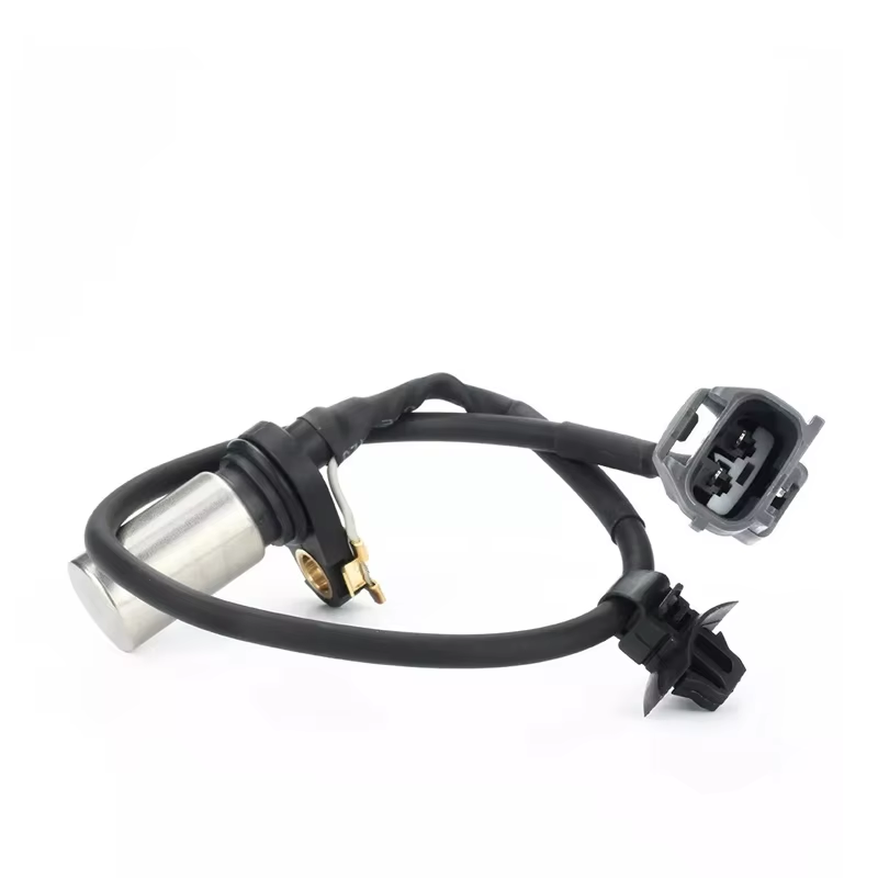
The crankshaft position sensor (CPS) helps synchronize the ignition timing and fuel injection, acting as a central part of the vehicle's engine management system. It monitors the position and rotational speed of the crankshaft.
What are the common signs of a failing crankshaft sensor?
Common signs include sudden engine stalling, persistent no-start conditions, misfires, power loss, reduced fuel efficiency, and tachometer drop-outs.
How often should the crankshaft sensor be replaced?
Replacement intervals vary by vehicle and usage. For instance, performance turbo vehicles are recommended to have the sensor inspected every 60,000 miles under normal conditions, but this decreases to 40,000 miles under high-stress conditions. Always refer to the manufacturer’s guidelines.
What causes crankshaft sensor failure?
Main causes are thermal stress, oil immersion, and electromagnetic interference from high-output ignition systems.
Can a crankshaft sensor issue affect fuel efficiency?
Yes, a malfunctioning crankshaft sensor can decrease fuel efficiency by 15–30% due to unoptimized injection cycles and increase in emissions.
Table of Contents
- Why Crankshaft Sensor Failure Matters: Impact on Engine Performance and Reliability
- Preventive Crankshaft Sensor Maintenance and OEM-Based Replacement Guidelines
- Diagnosing a Failing Crankshaft Sensor: Symptoms, Causes, and Real-World Failure Patterns
- Step-by-Step Crankshaft Sensor Testing and Physical Inspection Protocol
- FAQ