 EN

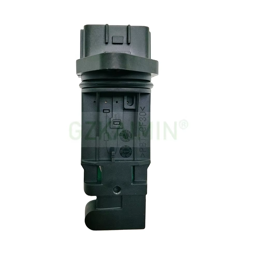
Choosing the correct air flow meter for an engine is not a matter of grabbing any part that looks similar. Gasoline and diesel powerplants breathe differently, and the sensor that reports intake volume to the engine control unit must match that behavior. A mismatched unit causes rough idle, poor fuel trim, and failed emissions checks. This guide explains how to match the right component by engine type, signal output, housing fitment, and calibration accuracy.
Why Engine Type Decides the Right Air Flow Meter
How a Mass Airflow Sensor Measures Incoming Air
An air flow meter, often called a MAF sensor (mass airflow sensor), sits in the intake tract between the air filter and the throttle body. Its core job is to measure the mass of air entering the engine, not merely its volume, because air density changes with temperature and pressure. Most units use a heated sensing element — a platinum hot-wire or a hot-film grid — that cools as air passes. The control module reads the electrical current needed to keep that element at a fixed temperature, then converts it to a mass-flow value.
Gasoline vs Diesel Intake Demands
Gasoline engines rely on a precise air-to-fuel ratio near stoichiometric combustion, so the mass airflow reading directly drives injector pulse width. Diesel engines run lean and use the sensor mainly for smoke-limit and boost control rather than metering fuel. That difference changes which air flow meter design fits. A diesel airflow meter often tolerates higher pulsation and oil mist from the crankcase breather, while gasoline units prefer cleaner, steadier flow. Matching the element type to the combustion strategy prevents erratic sensor output. Engine displacement and turbocharging further shift the required measurement range, so the rated flow capacity should exceed peak demand with margin.
Reading Signal Output — Analog, Digital, Hot-Wire, Hot-Film
Analog Voltage Output and ECU Mapping
Traditional air flow meter designs send a variable analog voltage, typically rising from around one volt at idle to about five volts at full load. The engine control unit compares that signal against a stored calibration map to calculate required fuel. If the replacement unit uses a different scaling curve, the ECU sees false airflow and trims the mixture. Always confirm the output type and the voltage range before ordering. Cross-check the part against the original equipment number to avoid a sensor with incompatible electronics. A voltmeter and a scan tool help confirm the idle and wide-open readings match the published curve before the vehicle returns to service.
Digital and Hot-Film Technologies
Newer mass airflow sensor families use a frequency or digital bus output, such as a square-wave signal or a controller-area-network message, instead of a plain analog line. Hot-film elements spread the heating across a thin ceramic substrate, giving faster response and stronger resistance to contamination than a thin platinum wire. SAE J1930 terminology standardizes these electronic diagnostic descriptions, which helps technicians match the correct module. Choose the technology that the engine platform was engineered for; swapping a hot-wire body into a hot-film application usually ends in fault codes.
Matching Housing, Flange, and Calibration
Physical Housing and Flange Fitment
Even a perfectly scaled air flow meter fails if it cannot bolt into the intake pipe. The housing diameter, flange pattern, and thread orientation must match the original tract. Some Japanese and European platforms use a clip-in body, while American trucks often need a screw-flange style. A loose or adapted flange creates an unmetered air leak that defeats the sensor entirely. Measure the bore, check the mounting style, and confirm the harness connector shape before purchase. ISO 1585 references related engine test conditions that assume correct intake sealing.
Calibration and Scaling
Calibration bridges the raw signal to a usable mass-flow number. Two sensors with identical housings can carry different scaling if they were mapped for a different displacement. The ECU integrates the airflow reading with intake air temperature and barometric pressure to set the final fueling. When replacing, prefer a unit programmed for the exact engine code. IEC 60068 environmental testing guides the durability of the sensing element under heat and vibration. Recalibrating a mismatched part by hand is impractical for most workshops and risks long-term trim errors. Record the old part number and the engine code on the work order so future replacements stay consistent and traceable.
Experience Case and Buying Advice
A Wrong-MAF Workshop Case
A fleet workshop fitted a gasoline van with a diesel airflow meter that shared the same housing shape. The vehicle started and idled, but drivers reported hesitation under load and a persistent lean fault. Diagnosis showed the sensor output rose too slowly for the gasoline calibration, so the ECU over-fueled to compensate. Swapping to the correct gasoline airflow meter restored smooth acceleration and cleared the code within one drive cycle. The case shows why the correct air flow meter depends on engine type more than visual similarity.
Inspect, Buy, and Maintain
Buy the air flow meter against the vehicle's original equipment listing, not by appearance alone. Inspect the sensing element for oil film or dust before fitment, since contamination skews the reading. Use a clean, dry harness and avoid pressing the fragile grid. During service, never spray cleaner containing solvents that attack the hot-film layer. Re-check the mounting seal after installation to prevent unmetered air. A matched, well-maintained unit delivers stable fuel trim and longer service life across gasoline and diesel applications.
Matching the right air flow meter starts with engine type, continues through signal output and housing, and ends with verified calibration. Gasoline and diesel units differ in element design, scaling, and contamination tolerance, so visual match never replaces a correct specification. Following the steps above keeps fuel trim stable, protects the catalyst, and avoids repeat diagnostics. Sourcing from a supplier with documented testing and clear fitment data reduces the risk of a wrong part reaching the bay.
Frequently Asked Questions
Question
What symptoms appear when mass airflow readings are incorrect?
Answer: Incorrect mass airflow readings cause rough idle, hesitation, and a lit check engine lamp. The air flow meter that reports false flow forces the ECU to miscalculate fuel, leaving the mixture too rich or too lean. Drivers notice poor throttle response and higher consumption. Cleaning rarely fixes a scaled-wrong unit. The reliable fix is fitting a correctly specified sensor for the engine platform and clearing learned trim.
Question
Why do gasoline and diesel units differ?
Answer: Gasoline engines meter fuel from the mass airflow value to hold a near-stoichiometric ratio, while diesel engines use the signal for boost and smoke control under lean combustion. The sensing element, scaling, and contamination tolerance vary with that role. A unit built for one strategy rarely satisfies the other. Matching by engine type prevents fault codes and unstable fuel trim across the service life.
Question
How is the correct signal type identified?
Answer: Check the original equipment listing for the output style, then compare with a voltmeter or scan tool. Analog units rise from low to high voltage with load, while digital or frequency outputs need a compatible ECU. Confirm the connector and pin layout before purchase. A mismatched signal type cannot be fixed by tuning and usually demands a correct replacement part.
Question
Can a diesel airflow meter fit a gasoline engine?
Answer: Some diesel and gasoline units share housing shape, yet the calibration and element behavior differ. Fitting a diesel part to a gasoline engine often causes slow sensor response and lean fault codes, as seen in workshop cases. Visual similarity never confirms compatibility. Always verify the engine code and published specification. The safe approach is selecting the exact unit the platform was engineered to use.
Question
Which inspection steps protect a new sensor?
Answer: Inspect the sensing element for oil film, dust, or solvent damage before fitment, and confirm the mounting seal is clean to block unmetered air. Use a dry, undamaged harness and avoid touching the fragile grid. Re-check the seal after installation. Sourcing from a supplier with documented testing and clear fitment data lowers the chance of a wrong part reaching the vehicle bay.